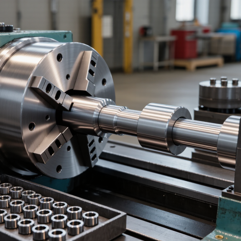
| Machine Overview | Roll Thread Machine | Forms external threads by cold-forming rather than cutting material away. | A cylindrical workpiece is pressed between hardened thread rolls. The rolls rotate and force the material into the required thread profile. | Produces threads with continuous grain flow, improved surface finish, and high repeatability when correctly set up. |
| Material Preparation | Workpiece or Blank | Provides the material that will be shaped into the finished threaded part. | The blank is supplied with a controlled diameter, length, chamfer, and material condition before entering the rolling zone. | Blank diameter and material ductility strongly affect thread height, pitch diameter, forming force, and dimensional accuracy. |
| Tooling | Thread Rolls | Transfer the thread geometry to the workpiece. | Precisely machined rolls engage the blank and displace surface material radially until the desired crest, flank, root, and pitch are formed. | Roll profile, pitch, hardness, alignment, and wear condition determine thread quality. |
| Tooling Support | Roll Spindles and Holders | Support and rotate the thread rolls while maintaining their position. | The spindles transmit torque from the drive system and hold the rolls at the correct center distance and angular relationship. | Rigid, accurately aligned holders help reduce vibration, taper, uneven loading, and premature tool wear. |
| Part Positioning | Work Rest or Support Blade | Supports the workpiece during rolling and helps establish its working position. | The workpiece rests against the support while the rolls apply forming pressure from above or from opposing sides, depending on the machine design. | Correct support height and condition are important for concentricity and stable part handling. |
| Part Handling | Guide, Stop, or Feeding System | Positions the blank consistently and controls entry and exit from the forming area. | Manual, vibratory, bar-fed, or automated systems may present each workpiece at a repeatable location and orientation. | Consistent loading improves cycle-time stability and reduces defects caused by mispositioning. |
| Power Transmission | Motor, Drive, and Gear System | Supplies controlled rotational power to the roll spindles. | The drive system synchronizes roll speed and transfers torque required to rotate the tools and the workpiece through frictional contact. | Speed and torque must match the material, thread size, roll design, and forming method. |
| Force Application | Hydraulic, Mechanical, or Servo Slide | Moves one or more rolls into the workpiece with controlled force and position. | The slide closes the tooling around the blank, maintains forming pressure, and retracts after the thread reaches the required dimensions. | Controlled force and stroke help prevent over-rolling, incomplete thread formation, and workpiece distortion. |
| Machine Structure | Frame and Bed | Provides a rigid foundation for the rolls, drive system, slides, and support components. | The frame absorbs forming loads and keeps the working components aligned throughout the cycle. | Structural rigidity contributes to dimensional consistency, low vibration, and longer tool life. |
| Process Control | Control Panel and Sensors | Controls operating parameters and monitors machine status. | Controls may regulate cycle timing, roll movement, feed position, lubrication, guarding, and fault conditions. | Monitoring improves repeatability and helps detect abnormal pressure, position, speed, or safety conditions. |
| Cooling and Lubrication | Lubrication or Coolant System | Reduces friction and heat at the roll-to-workpiece interface. | Lubricant is delivered to the forming zone to support material flow and reduce adhesive wear on the rolls. | Proper fluid selection, filtration, and delivery can improve surface finish and extend tool life. |
| Safety | Guarding and Interlock System | Protects operators from rotating tools, pinch points, chips, and unexpected machine movement. | Enclosures, access doors, emergency stops, and interlocks restrict access to the forming area during operation. | Safety devices should remain functional and should not be bypassed during setup or production. |
| Operating Principle | Radial Thread Forming | Creates the thread by displacing material instead of removing it with a cutting edge. | As the rolls penetrate the blank, material flows outward and fills the spaces between the thread-forming ridges. | Because no chips are produced during forming, the process can offer efficient production and strong thread geometry. |
| Operating Principle | Through-Feed Rolling | Produces threads on suitable parts that can travel continuously through the rolls. | The workpiece enters one side of the rotating rolls and exits the other side after the thread profile has been formed. | Well suited to high-volume production of parts with consistent thread locations and accessible rolling areas. |
| Operating Principle | Infeed or Plunge Rolling | Forms a thread over a defined length while the workpiece remains in a controlled position. | The rolls move radially into the stationary or positioned workpiece and then retract after the forming cycle is complete. | Useful for shoulders, blind thread sections, or parts that cannot pass continuously through the tooling. |
| Quality Control | Thread Inspection | Verifies that the finished thread meets dimensional and functional requirements. | Inspection may include pitch diameter measurement, thread gauges, visual checks, surface inspection, and verification of thread length and location. | Regular inspection helps identify roll wear, incorrect blank size, misalignment, or unstable forming conditions. |