| Required buoyancy | Calculated from the buoy’s displacement, the mass of the buoy and attached equipment, and the supported portion of the mooring system. | Buoyancy must be sufficient for the intended load while retaining an engineered reserve. The required reserve depends on the application and design criteria. |
| Displacement calculation | For a floating body, buoyant force is based on the mass of the displaced water. Seawater density is commonly taken as approximately 1,025 kg/m³ for preliminary calculations; actual density varies with salinity and temperature. | The calculation helps determine the submerged volume and expected draft. It is not a substitute for a complete stability and mooring analysis. |
| Buoy dimensions and shape | Diameter, height, profile, draft, and freeboard are selected to meet buoyancy, stability, visibility, handling, and site requirements. There is no single standard size for all mooring buoys. | Design inputs include water depth, wave and current conditions, mooring loads, installation method, and any navigation or access requirements. |
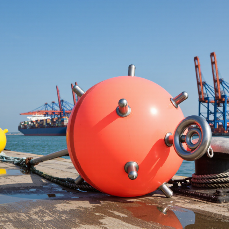
| Outer shell | Common construction options include rotationally molded, UV-stabilized polyethylene shells and fabricated steel shells. The appropriate material depends on service conditions and the design. | The shell protects the buoy core from impact, abrasion, sunlight, and water ingress. Shell thickness and reinforcement should be specified for the expected loads and handling. |
| Foam core | Closed-cell polymer foam is selected according to required buoyancy, water-absorption performance, compatibility with the shell, and service temperature. | Closed cells limit water uptake if the shell is damaged. Foam type and density should be documented and verified against the design specification. |
| Load-bearing hardware | Central rods, plates, eyes, or other load-transfer components are sized for the specified mooring loads and connected to the buoy structure. | Hardware and its attachment points carry concentrated forces. The design should account for fatigue, corrosion, and the direction of applied loads. |
| Corrosion protection | Metal components may use suitable corrosion-resistant alloys, coatings, or galvanizing, selected for the water and exposure conditions. | Material selection should consider seawater exposure, dissimilar-metal contact, maintenance access, and the expected service life. |
| Shell forming | For a molded polyethylene design, the shell is formed in a mold using a controlled heating and cooling process. Fabricated designs use their specified cutting, forming, joining, and coating procedures. | Process controls help achieve consistent geometry, wall thickness, and finished surfaces. The production route depends on the chosen shell material. |
| Foam installation | The specified foam core is placed, fitted, or introduced using the method appropriate to the buoy design. Seams and openings are closed according to the product construction. | Correct fit and sealing help reduce voids and limit water entry. Inspection should confirm that the core and shell are assembled as specified. |
| Assembly and finishing | Load-bearing hardware, protective fittings, identification markings, and any specified reflective or visibility features are installed. | Fittings must not obstruct inspection or interfere with the mooring arrangement. Markings and colors should follow applicable project or navigation requirements. |
| Quality checks | Checks may include dimensional inspection, visual examination, hardware and attachment inspection, buoyancy or flotation checks, and review of material and production records. | Acceptance criteria should be defined in the purchase specification. Load testing, when required, should follow an agreed procedure and documented test limits. |
| Final mooring-system verification | Buoy capacity and connections are reviewed together with the chain or rope, anchors, water depth, and environmental loads. | A buoy’s rating alone does not establish the capacity of the complete mooring system. System-level engineering is needed for safe deployment. |